+


1PCS 16-Kanal PWM Lenkgetriebe Fahrer Bord Modul Controller IIC Interface Fahrer Modul
16 channel PWM steering gear drive board controller USB serial port TTL IIC interfaceThe main parameters are as follows:1. 16 channel PWM drive is fully led out, and IIC communication is used to control LED, steering gear and other equipment2. The module has the function of USB to serial port, which is convenient for computer and raspberry piesignal communication3. It is compatible with raspberry pie interface and can also be controlled by ardunio4. The working voltage is 5V, which can be powered by micro USB or directly 5VSteering gear control1. First download the program to the control board, and the ardunio nano board passesConnect Mini usu to the computer, open the routine, setting board, port, etc. in ardunio software, then click compile, and the compilation passes,Then upload the program. Connect the circuit and download the program. Press the tap switch, and the steering gear will turn forward 45 degrees, and then reverse 45 degrees.

16 channel PWM steering gear drive board module parametersVoltage: dc5-10v power supplyCommunication interface: IIC 16 channel steering gear controlProduct size: 25mm*61mmNet weight: 11g
When you are in a project, you encounter the PWM output of the microcontroller chipIf the output pin is not enough, then this pca9685, 16 way rudderMachine can help you solve this problem quickly, as long as your main control coreWith I2C communication, the chip can make the main control chip and pca9685Communication, realizing the simultaneous control of multiple actuators, pca9685, 16 channelsThe steering gear adopts 12C communication, with a built-in PWM driver and aClock. This means that this will be very different from the tlc5940 series.You don't need to constantly send signals to occupy your MCU! It is 5 ∨Compatible, which means you can also use 3.3V MCU to control and installAll ground drive to 6V output (when you want to control the white or blue indicator lightIt is also possible to use 3.4+ positive voltage) 6 address selection pins so that you canHang 62 drive boards on a single 2C bus, with a total of 992 channelsRWM output. That will be a huge resource. About 1.6kHz adjustableFrequency PW output, ready to output 12 bit resolution for stepper motor, whichIt means that the update rate at 60Hz can reach 4 υ S resolution, configurableThe push-pull output or open circuit output of, and the output enable pin can be quickly disabledAll outputs.
Features of 16 channel PWM actuator drive board moduleThe pca9685 chip is wrapped in the center of the small board, the power input terminalThe green power indicator is convenient for you to plug in 16 servo motors at one time in 4 groups of 3-pin connectors (the plug of servo motor is slightly wider than 0.1 ",So you can put 4 pairs of 0.1 connectors) the reverse polarity protection cascade design V input on the terminal block+Place a large capacitor on the line (you will need it in some cases). The maximum input voltage of the periphery depends on thisA 220 ohm series resistor is placed on all PWM output lines of the 10v1000u capacitor to protect them and easily drive the LED.
16 channel steering gear control board module USB serial port TTL Bluetooth parametersMaster chip: STM32 seriesMain frequency: 48mhzSize: 43.5mmx36mmx12mmMounting hole position: 37mmx30mm, aperture 3mmService temperature: -40 ℃ ~80 ℃Working voltage: USB power supply 5V TTL power supply (one out of two), steering gear power supply voltage 5-7.2vSteering gear steering gear channel: 16 channelsPww accuracy: 0.1usLimited step size of steering gear: 1USMotor control frequency: 25kHzCommunication interface: USB TTL (Bluetooth optional)Baud rate: 115200~2400kpsUpper computer software: YesNumber of action groups: 16 groupsNumber of stored actions: 8192Multi slice cascade expansion: support

16 channel steering gear control board module USB serial port TTL Bluetooth introductionSmall sizeThe size of steering gear control board is 43.5mmx36mm, which is very compact and high qualitySeparate steering gear power supplySteering gear power supply 5-7.2vHigh performance processorIt adopts 32-bit imported high-performance processor and powerful data processing ability to control the operation of the equipment with high precisionDrive 16 channel steering gear with rich interfacesIt supports driving 16 channel steering gear at the same time, and the steering gear control is accurate and stableExternal signal input1N3 --- GND short circuit, execution action group 01n2 --- GND short circuit, execution action group 11N1 --- GND short circuit, execution action group 2Multiple communication modesSupport multiple communication modes, USB interface, tll serial port and Bluetooth (optional)Bluetooth communicationOptional Bluetooth mode, convenient wireless interconnection with mobile phone or PC, remote control operationFunction switchStop and operation of control program1. USB interfaceDirect plug without drive2. Action GroupYou can customize the sequence of action groups, inOffline to the control board. Offline operation3. Serial portTTL serial port, convenience and MCU or serial port tool connection4. Steering gearDrive 16 way steering gear and speed at the same timeAdjustable, isolated drive, stable performanceFixed and unburned plate5. Bluetooth interfaceOptional Bluetooth control moduleConnect to PC or mobile phone wirelesslyRemote control operation6. Simple controlJust define the target action supportPC graphical debugging

Introduction of aircraft model motor tester electric regulator(1) Output: ≤ 15mA (5.0)(2) Input: DC 4.2-6.0v(3) Output signal: 1.5ms soil 0.5ms(4) Size: 46*32* 17mm(5) Weight: 8g(6) Adjustment mode: manual, automatic, middle positionFeatures: it can easily detect and set the virtual position, jitter and middle position of the server, and can connect two groups of steering gear or electric regulator; Single chip microcomputer control, good stability and high precision. Rotate the knob to detect the steering gear.If you connect the electronic governor (brush or brushless), you can get rid of the remote control equipment for manual speed regulation. It is very practical to test the performance of the governor or motor, and there is no need to connect the remote controller and receiver.It is equivalent to a "manual receiver" function, which simulates the steering of the transmitter through the knob
Aircraft model motor tester - Characteristics of electric regulatorReferring to the following picture, the left side is connected to the steering gear, which is divided into three groups: upper, middle and lower, and can be connected to three steering gears; The single row pin on the right is connected to the power supply, and the negative pole (see the identification symbol) near the side is connected to the negative pole of the battery,Be sure not to connect it reversely. If the power supply is connected reversely, the pin corresponding to the IC identifier will be burned, so don't worry. Turn on the power, the blue light will be on at the same time, and then only the first one on the left will be on,For manual adjustment potentiometer test, press the key, the middle light is on, which is the centering test: the third light is on, and the automatic test. The connection method of testing the electric regulator is the same as that of the steering gear,But don't connect the power supply at the input end. The test motor needs to be connected to the electric regulator first, which is the same as the test electric regulator!Basically mark the upper pin, control and indicator of the steering gear tester. The pin corresponding to the s flag is of little use here and can be ignored. The steering gear connected to the left can be divided into three groups: upper, lower and middle, which can test three steering gears at the same timeConnect the power supply from the single row pin on the right, the three blue lights will light up at the same time, and then the light onthe left will light up. At this time, you can select the three modes through the mode selection buttonWhen the light on the left is on, it is in the manual adjustment mode. You can directly use the potentiometer (and the adjustment knob) to control the rotation of the steering gear, and then press the button. The middle light will be on. At this time, it is the centering test. Pressthe button again The light on the right will be on, which is for automatic test. The steering gear will rotate continuously, and then rotate in the opposite direction after it is stuck. One cycle. The connection method of testing the electric regulator is the same as that of the steering gear. When testing the motor, you need to connect the electric regulator first. The method is all according to the above steps

Product description of DC stepping motor actuator drive board moduleThe original adafruit motorshield kit is one of our favorite kits, which is why we decided to make something better. We have upgraded the shielding kit,A simple way to drive DC and stepper motors. This makes your next robot project work fast! We have been able to drive up to four DC motors or two stepper motors, but many improvements have been added:Instead of i293d Darlington drive, we now have tb6612MOSFETDriver: 1.2A and 3a peak current capability per channel. It also has a low voltage drop across the motor, so you get more torque from your battery and have a built-in flyback diode.We don't use the PWM pin of lock and Arduino. We have a completely dedicated PWM driverOn chip. This chip handles all motors and speed control12C。 Only two pins (SDA and SCL) are required to drive multiple motors, becauseAs it is I2C, you can also connect any other 12C device or shieldTo the same pin. This also makes it compatible with any Arduino and completelyStacking design: 5 address selection pins means up to 32 stackableStack this is 64 step motors or 128 DC motors! Many other minor changesFor example, the polarity protection FET on the power pin and some prototype areas oThe shield is assembled and tested here, so all you have to do isSolder on straight or stacked head and terminal blocks. Let's take a look at these specifications: 2 hobby servo connected to 5V, high-resolution dedicated timer connected to Arduino_ No jitter!4h - bridge: tb6612 chipset provides thermal shutdown protection and internal return protection diode for each bridge (3a peak). It can be at 4.5vdc Run the motor to 13.5vdc Up to 4 bidirectional DCMotor with 8-bit speed selection (therefore, about 0.5% resolution)Up to 2 stepper motors (single pole or double pole) with single coil, double coil, crossover or micro step. The power supply of electricvehicles is automatically disabled, and the large junction box connector is easy to connect wires(18-26awg) and power supply Arduino reset button bring top polarity protection 2-pin terminal block and jumper to connect external power supply for independent logic / motor power supply test compatibilityArduino uno, Leonardo, rightful / megar3, expired, reduplicated Mira and duemi lanove. Use mega/ should 2, and use 2 jumpers earlier. download Easy to use Arduino software library, with a shield for assembly and testing, terminal block, common head, jumper. Some welding is required to assemble the head. Stack heads not included
Brief introduction of DC stepper motor actuator drive board moduleStrong enough motor drive board, steering gear, stepping motor and DC small motor are all done. There are not enough motors in the 12C interface. If one is superimposed, the number of driving motors will be doubled.1. Perfectly compatible with the expansion of Arduino interface2. Through I2C and Arduino communication, the address can be modified3. Two steering gears can be connected to directly output PWM drive4. It can be connected to 4 DC brush motors or 2 4-wire stepper motors5. TB6612FNG motor drive chip is used, with 1.2A drive capacity, peak value of 3.2a, and spike L298N module
Model Number : NK-DE29H3
Type : Voltage Regulator
Origin : Mainland China
Supply Voltage : DC5-10V
Condition : New
Application : Universal
Operating Temperature : -40℃~+80℃
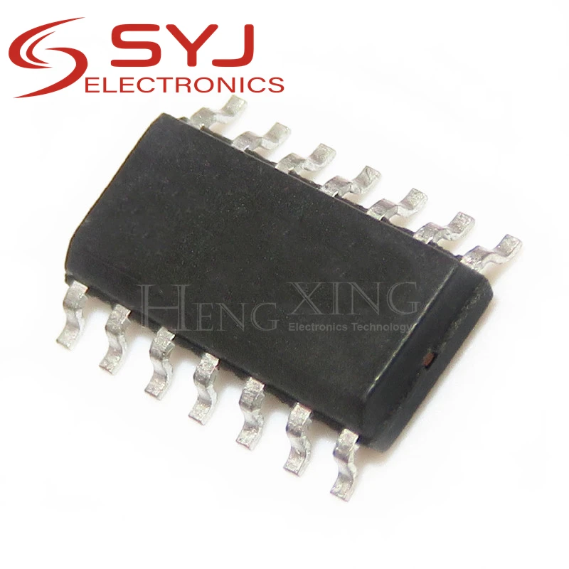
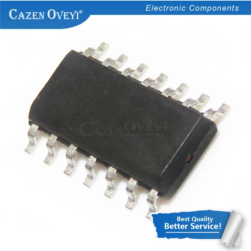
Package : SOP