+


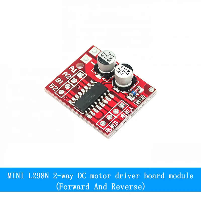
DC Motor Drive Module Reversing PWM Speed Dual H Bridge Stepper Motor Mini Victory L298N

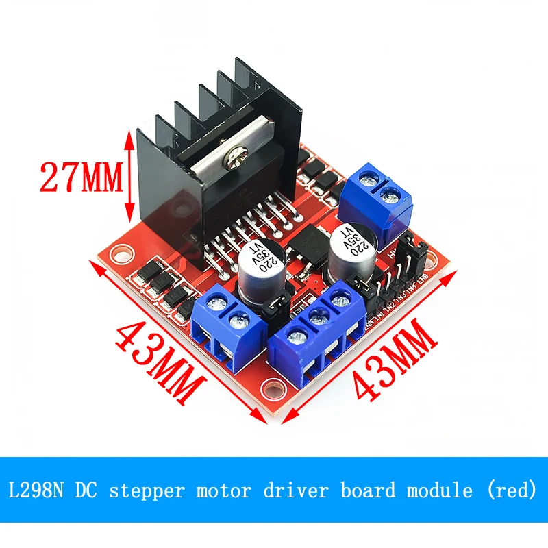
Parameter:Module name: Double H-bridge motor driver moduleWorking mode: H bridge drive (dual)Main control chip: L298NLogic voltage: 5VDriving voltage: 5V-35VLogic current: 0mA-36mADrive current: 2A (MAX single bridge)Storage temperature: -20℃ to +135℃Power: 25WWeight: 30gOuter size: 43*43*27mm
Precautions:1. When your driving voltage (marked as 12V input in the picture above, the actual acceptable input range is 7-12V) is 7V-12V, you can enable the onboard 5V logic power supply. After using the onboard 5V power supply , +5V in the interfaceThe power supply does not need to input voltage, but it can lead to 5V voltage for external use. (This is a regular application!)
2. When the driving voltage is higher than 12V, less than or equal to 24V (it is suggested in the chip manual that it can support up to 35V, but according to the
It is great to test the general 298 conservative application voltage to support 24V! ), for example to drive a rated voltage of
18V motor. First, the jumper cap that enables the onboard 5V output must be removed. Then connect 5V externally to the 5V output port
5V enable is a control signal with a level of 5V. When the signal input is valid and the power supply in the motor drive module is normal, the motor drive module outputs current. Otherwise, even if the power supply is normal, there will be no current on the motor.The voltage supplies power to the internal logic circuits of the L298N. (This is an unconventional application of high voltage drive!)
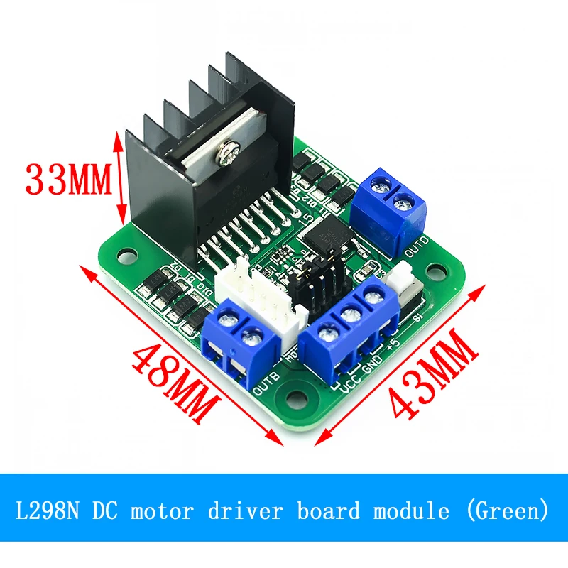
Product parameters:1. Driver chip: L298N dual H-bridge DC motor driver chip2. The power supply range Vs of the terminal of the drive part: +5V~+35V; if you need to take power on the board, the power supply range Vs: +7V~+35V3. Drive part peak current Io: 2A4. Logic part terminal power supply range Vss: +5V~+7V (+5V can be taken on board)5. Logic part operating current range: 0~36mA6. Control signal input voltage range: Low level: -0.3V≤Vin≤1.5V High level: 2.3V≤Vin≤Vss7. Enable signal input voltage range: Low level: -0.3≤Vin≤1.5V (control signal is invalid) High level: 2.3V≤Vin≤Vss (control signal is valid)8. Power consumption: 20W (at temperature T=75℃)9. Storage temperature: -25℃~+130℃10. Driver board size: 48mm*43mm*33mm (with fixed copper column and heat sink height)11. Weight of driver board: 33g12. Other extensions: control direction indicator lights, logic part on-board power-taking interface.
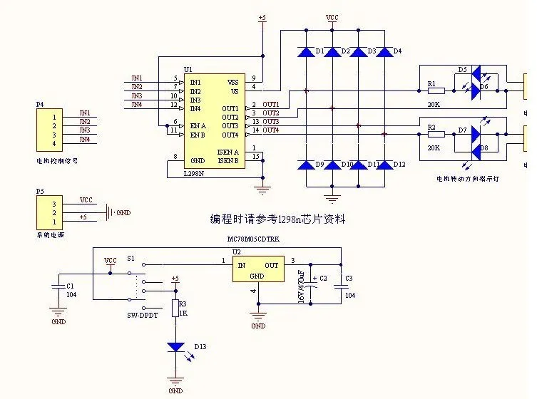
Instructions for use:Driving of stepper motor: It is valid when ENA and ENB on the board are high level, and the level here refers to TTL level. ENA is the enable terminal of A1 and A2, and ENB is the enable terminal of B1 and IB2. BJ is connected to the common terminal of the stepper motor.The control logic of the stepper motor is as follows, where A, B, C, and D are the four coils of the stepper motor. A value of 1 indicates that there is current passing through, and a value of 0 indicates that no current is flowing. The wiring diagram of the coil is shown in the figure below (take a four-phase stepper motor as an example)
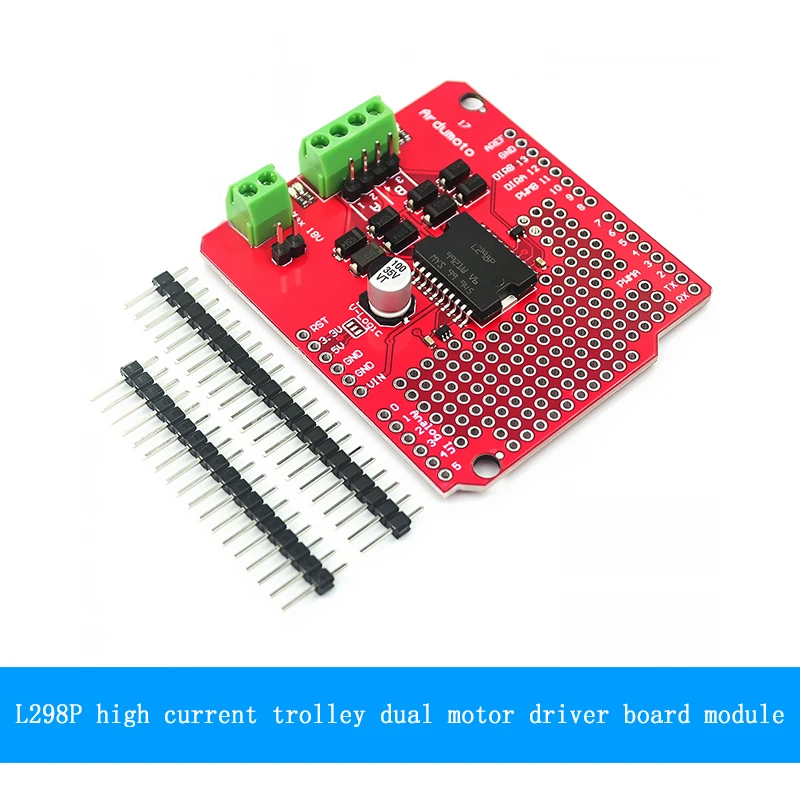
Robot peripheral L298n motor driver board
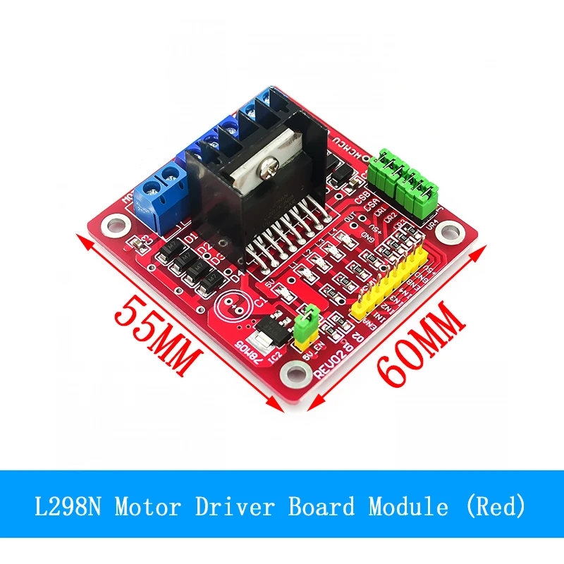
Product Description:This L298N driver module adopts the L298N chip of ST company, which can directly drive two 3-30V DC motors, and provides a 5V output interface, which can supply power to the 5V microcontroller circuit system, supports 3.3VMCU control, and can easily control the speed of the DC motor And direction, can also control 2-phase stepper motor, is a smart car.
Product parameters:1. Driver chip: L298N dual H-bridge driver chip2. The power supply range of the drive part terminals VMS: +5V ~ +35V3. Drive part peak current Io: 2A/bridge4. Logic part terminal power supply range Vss: 4.5-5.5V5. Logic part operating current range: 0~36mA6. Control signal input voltage range: high level 4.5-5.5V low level 0V7. Power consumption: 20W8. Storage temperature: -25℃~+130℃9. Driver board size: 55mm*60mm*30mm10. Weight of driver board: 33g11. Other functions: control direction indicator, power indicator, current detection, logic part on-board power-taking interface.
Product parameters:
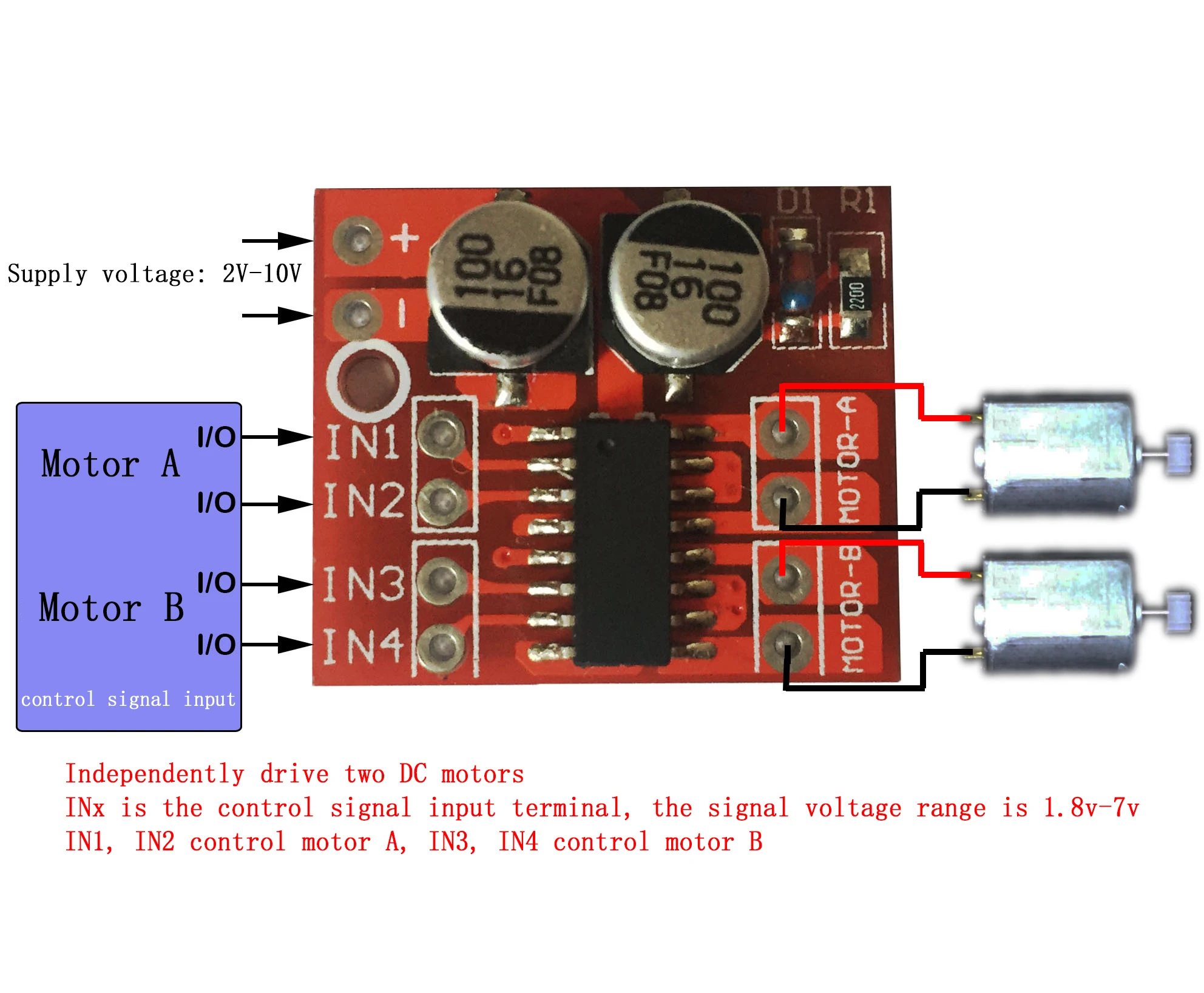
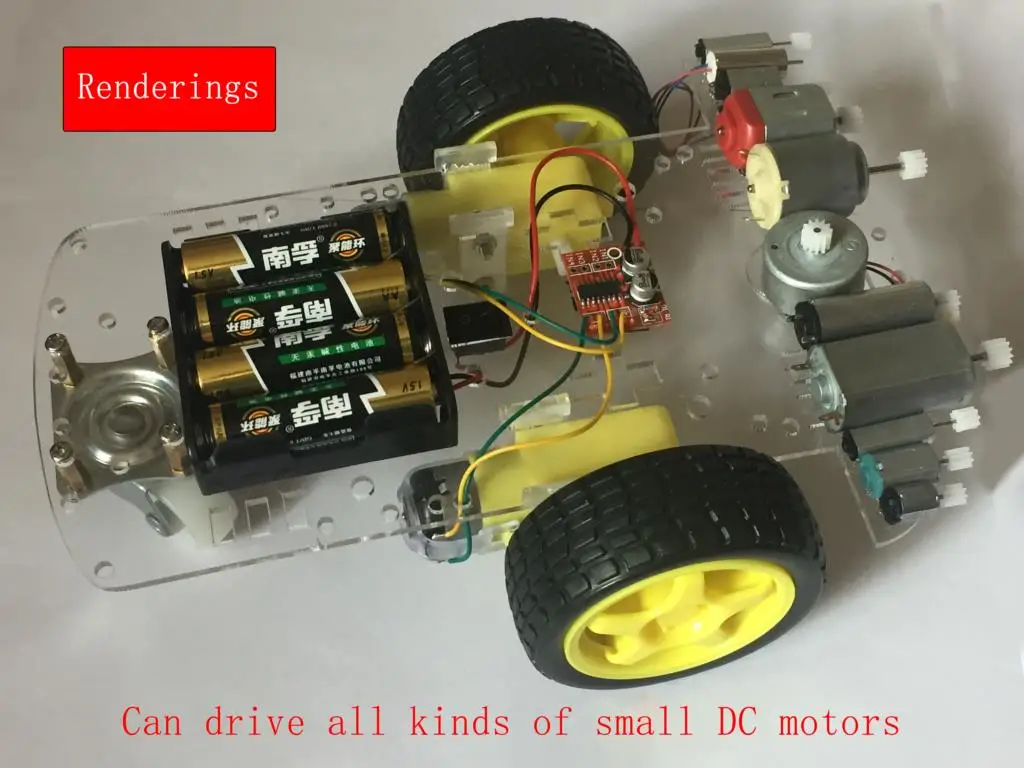
Dual H-bridge motor drive, can drive two DC motors or one 4-wire two-phase stepper motor at the same time;Module power supply voltage 2V-10V;Signal terminal input voltage 1.8-7V;Single-channel working current 1.5A, peak current up to 2.5A, low standby current (less than 0.1uA);Built-in anti-common conduction circuit, when the input terminal is suspended, the motor will not malfunction;Built-in thermal protection circuit (TSD) with hysteresis effect, no need to worry about motor stall material:
INx is connected to the microcontroller IO or other signal sources, and MOTOR-A and MOTOR-B are connected to the motor.
Precautions:
1. The reverse connection of the positive and negative poles of the power supply will definitely cause circuit damage.
2. When the output is short-circuited to ground or the output terminal is short-circuited, and the motor is locked, the chip will be thermally protected, but the chip will be burned when the voltage is close to or exceeds 10V and the peak current greatly exceeds 2.5A.
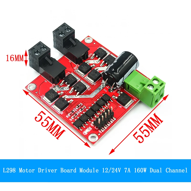
Product introduction: Double H bridge, can drive two DC motors at the same time, single channel 7A high power; wide voltage 6.5V ~ 27V; optocoupler isolation input signal; with isolation and undervoltage protection; Relief circuit, stable and reliable, industrial grade.
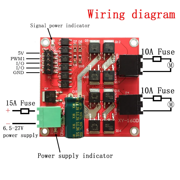
Product Highlights:1. Double H bridge, can drive two DC motors at the same time, single 7A current, high power;2. Wide voltage input 6.5V~27V;3. Signal optocoupler isolation input, which can be directly controlled by IO port without interference;4. Under-voltage protection to prevent instantaneous high current from burning the module;
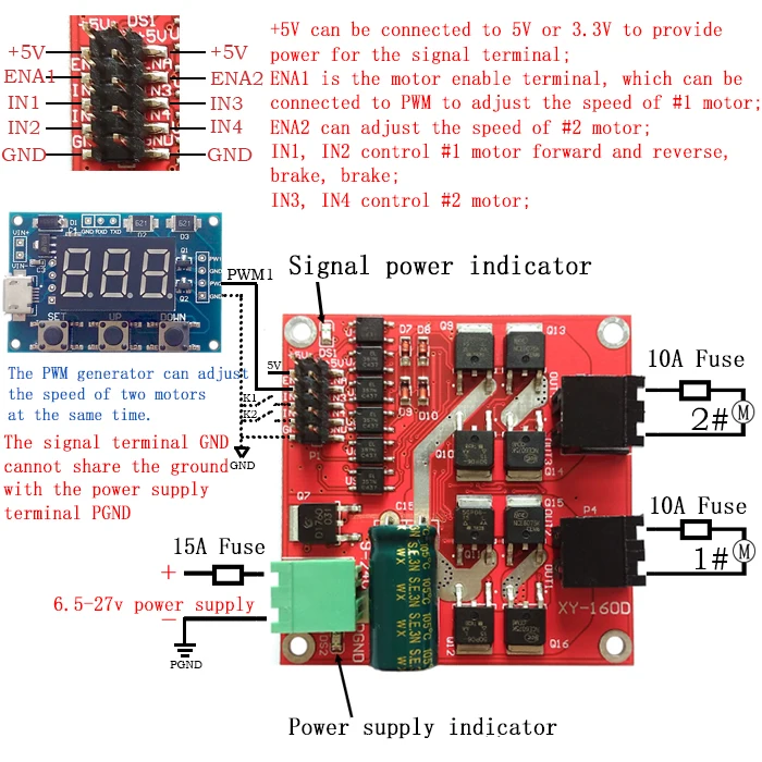
Product parameters:1. The power supply voltage is 6.5V-27V. The power supply must not be reversed or exceed 27V, otherwise the module may be burned. It is recommended to connect a 15A fuse in series at the power input end.2. Dual motor interface, rated output current of each channel is 7A, peak current is 50A, the motor interface must not be short-circuited, it is recommended to connect a 10A fuse.3. The control signal voltage is 3-6.5V, which are the enable signal and the forward and reverse control signals respectively.4. The enable signal terminal (ENA) input PWM adjustable speed, PWM frequency range 0-10KHZ, PWM small pulse width 10us.5. Working temperature -25℃-80℃.6. Product size: 55*55*16mm (length, width and height).7. The diameter of the mounting hole: 3mm. When installing, pay attention to prevent short circuit of the back circuit. You can add insulating pads or copper pillars to raise the circuit board.8. Weight: 20 g.
Suitable motor parameters:A motor with a rated voltage of 24V, suitable for a motor with a rated power of 115W and below or a motor with a rated current of 7A or less for a long time at full capacityA motor with a rated voltage of 12V, suitable for a motor with a rated power of 40W and below or a motor with a rated current of 7A or less for a long time at full capacity
Precautions:1. The power supply of the driver must not be reversed. It is recommended to connect a 15A fuse in series at the power interface, and the voltage should be between 6.5 and 27V. If the voltage is overvoltage, the power-on may burn the drive module.2. It is recommended that the rated output current of the power supply be more than 2 times the rated current of the motor, so as not to cause the power supply to fail to provide the current required by the motor to start, and to cause the power supply voltage to drop so that the power supply voltage cannot reach the input voltage required by the drive, so that the drive module performs under-voltage protection shutdown. If the output is cut off, the motor will stop.3. The motor interface must not be short-circuited, otherwise the drive module may be burned. It is recommended to connect a 10A fuse in series at the motor interface.4. When switching between forward and reverse rotation, it is necessary to brake for more than 0.1S before reverse rotation. It cannot be reversed before the motor has stopped, otherwise the driver may be damaged.5. When the drive module is powered off, do not directly or indirectly rotate the motor at high speed, otherwise the electromotive force generated by the motor may burn the drive module. If the application needs to rotate the motor at high speed when the driver module is powered off, it is recommended to connect a relay (NO and COM terminals in series) to the motor interface of the driver, and the relay coil and the driver share the same power supply. In this way, when the power fails, the relay will disconnect the drive from the motor.6. Be careful not to get the driver wet, do not short-circuit the components on the driver board, and do not touch the pins and pads of the components on the board with your hands.
Art : der Regulierungssteller
Bedingung : Neu
Betriebstemperatur : -40-+85
Anwendung : Computer
Markenname : Si Tai&SH
Modellnummer : DC Motor Drive Module
Ursprung : CN (Herkunft)
Ableitungs-Energie : 2.5A
Versorgungsmaterial-Spannung : 1.8-7V
ist individuell : Ja
Paket : Module