+


Ddcsv 3,1 Upgrade Ddcsv 4,1 4-achse G-code Cnc Offline Controller + Hybrid Servo Motor Kit + 3d Rand Finder E-stop Mpg 75w24v Dc

DDCS V4.1 is a 3/4 axis offline motion controller upgraded on the basis of DDCS V3.1, V2.1 and V1.1. DDCS V4.1 inherits the consistent simple and efficient features of DDCS series, and according to the shortcomings of DDCS V3.1, it improves the algorithm, adds programming instructions, rotation instructions, etc., improves the simulation function, etc., supports IO port configuration, etc., The product function of the DDCS CNC controller has been improved as a whole, making its function more stable and powerful, and more suitable for the needs of customers.DDCS V4.1 CNC system adopts ARM+FPGA design structure, ARM completes the man-machine interface and code analysis part, FPGA completes the underlying algorithm and control pulse generation part, and the fpga speed generator adopts a 32-bit speed generator, which makes the speed and acceleration resolution higher rate. Reasonable design, reliable control and convenient operation, DDCS V4.1 enhances product functions and panel layout structure, but 17 keys can still complete all offline control operations. DDCS V4.1 also supports the universal FANUC compatible G instruction set.DDCS V4.1 inherits the main functions of DDCS V3.1. For users who are proficient in using 3.1, combined with this manual, they can quickly master the operation method of DDCS V4.1 and use its functions proficiently. It is hoped that major users will read carefully before powering on the controller.Manual, you can operate this controller proficiently.
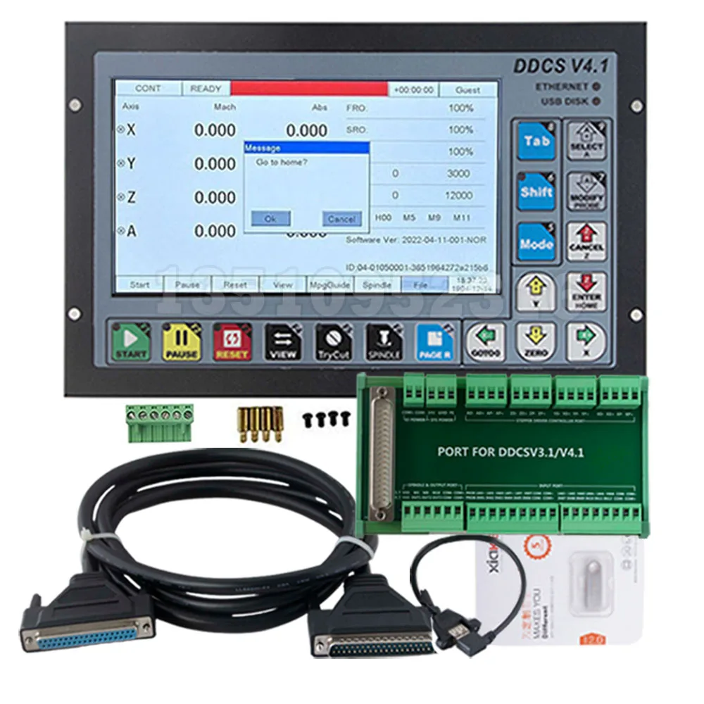
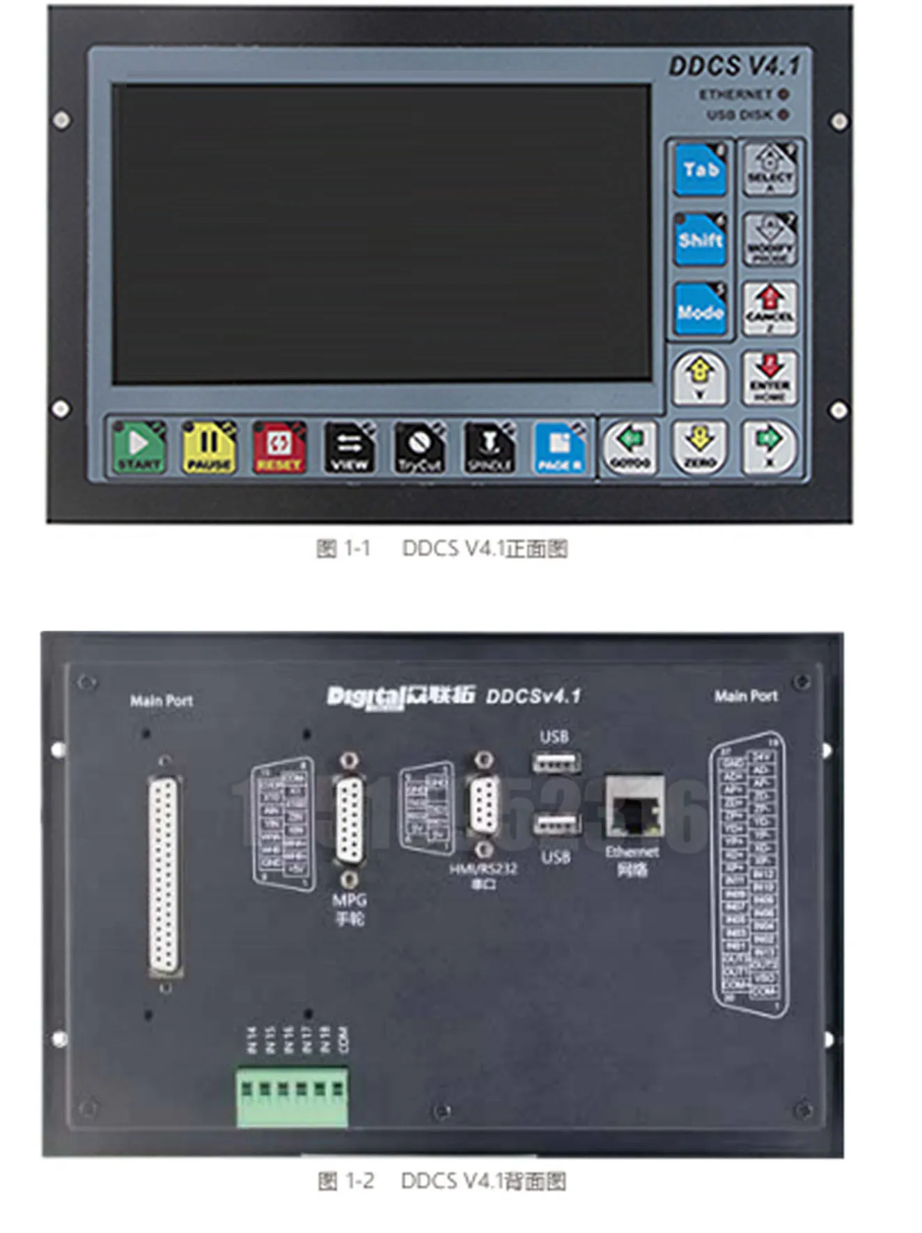
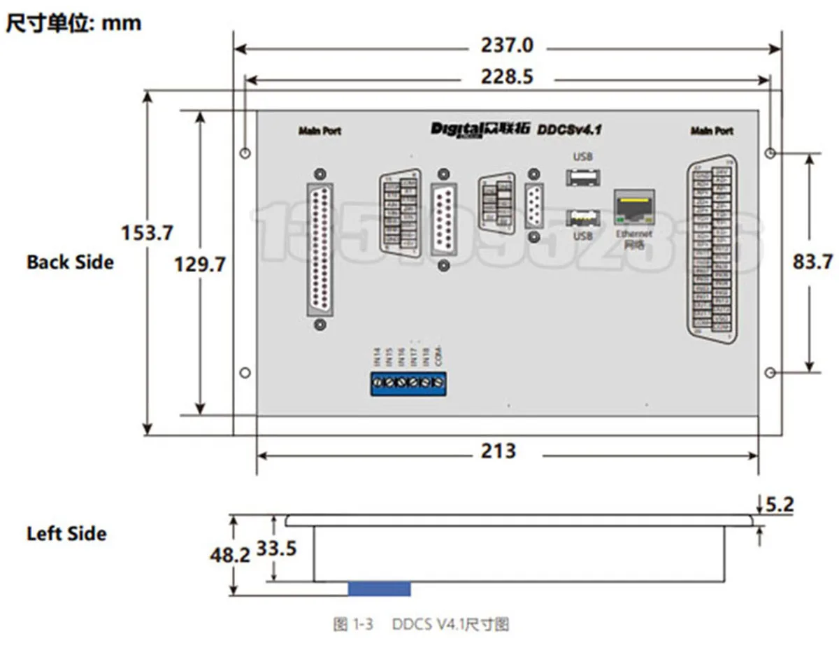
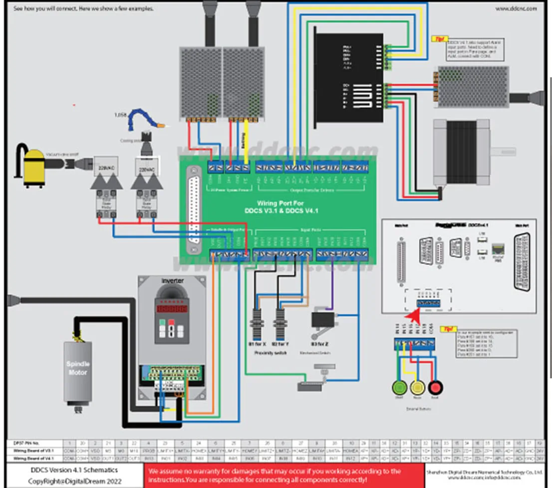
DDCS V4.1 brief performance parameters:1) 7-inch screen, 17 keys; 18 optocoupler isolated digital input interfaces, 3 optocoupler isolated digital input ports;2) The new version strengthens the algorithm, and introduces a new algorithm for motion planning, which makes the path of small line segments smoother through configurable contour errors;3) 1 channel 0-10V spindle speed control analog output interface, and the spindle can be configured as a servo spindle;4) 3-4 axis drive mode adopts differential mode and double pulse mode for customers to choose, the maximum output frequency of interpolation pulse is 500Khz;5) ARM9 main control chip, FPGA core algorithm chip;6) 7-inch TFT screen; size: 1024x600 pixels, resolution: 72 pixels/inch; the controller has 17 operation keys;7) The main control device is 24VDC power input, and the current capacity is not less than 0.5A; the IO port power input is also 24VDC, and the current capacity is not less than 0.5A; the main control power supply power supply control system, the IO port power supply power supply IO; when When the IO port is not powered, all IO ports are invalid;8) Support standard MPG;9) Support single-axis manual jogging and linkage and fixed-distance operation of panel buttons;10) Support running specified line and nearest point operations;11) Support floating tool setting, fixed tool setting, corner point setting and tool length measurement12) Supports array processing, sequential processing, plane milling and cylindrical milling;13) Support the offset adjustment of XYZA four-axis;14) Support pause breakpoints, power-off breakpoints and load breakpoints15) Support multi-workpiece origin operation, users can save origin and load origin as needed16) Support the centring operation of X and Y axis;17) Support simulation operation and during simulation, you can adjust the magnification to carefully observe whether the programming path is in line with expectations, and perform software limit check. During simulation, you can pause at will. After pressing the start button, the system will stop from the simulation pause breakpoint. start execution18) The communication between the controller and the computer can be realized through the Ethernet connection port, which is convenient for operations such as file reading and copying;19) The memory of the controller is 1G; the G command can also be read from the U disk, and the file size of the G command is not required;20) The language of the controller adopts international coding, and supports all languages. Customers can make language packs of various characters according to their own needs;21) DDCS V4.1 controller only supports NPN type limit switch;22) The use rights of the controller include operator, administrator and super administrator.New features compared to the old version of DDCS V3.1:1) Added file transfer via Ethernet;2) The mapping axis function is added to the CNC function (can be used to configure the double-Y gantry structure machine);3) The spindle can also be configured as a servo spindle;4) Added bias adjustment;5) The polar coordinate programming command and rotation command are added to the command, and the radius compensation command is perfect;6) The motion planning introduces a new algorithm to make the path of small line segments smoother through configurable contour errors;7) A total of three detection functions are supported: corner detection, inner circle center detection, and outer circle center detection;8) Improve the specified line start function and the nearest point start function, no matter how large the file is, it can be quickly started within a few seconds;9) Improve the simulation function. During the simulation, you can adjust the magnification to carefully observe whether the programming path meets the expectations, and perform a software limit check. During the simulation, you can pause at will. After pressing the start button, the system will start from the simulation pause breakpoint. implement;10) In terms of input port, the port function can be configured arbitrarily, and the driver alarm support is added;11) For the a-axis, a cyclic encoder is added. The cyclic encoder is especially useful for processing files where a keeps growing;12) There is also a parsing error prompt. DDCS V3.1 has never been there, and if there is a parsing error, it will stop directly;13) The language adopts international coding, which supports basically all languages. The advantage is that it can be used as a language pack of various characters;14) Increase the emergency stop acceleration configuration parameter to solve the huge impact caused by the direct stop when the machine tool moves at high speed;15) FPGA speed generator adopts 32-bit speed generator, and the resolution of speed and acceleration is higher.

Introduction:
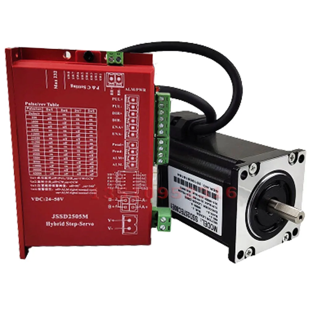
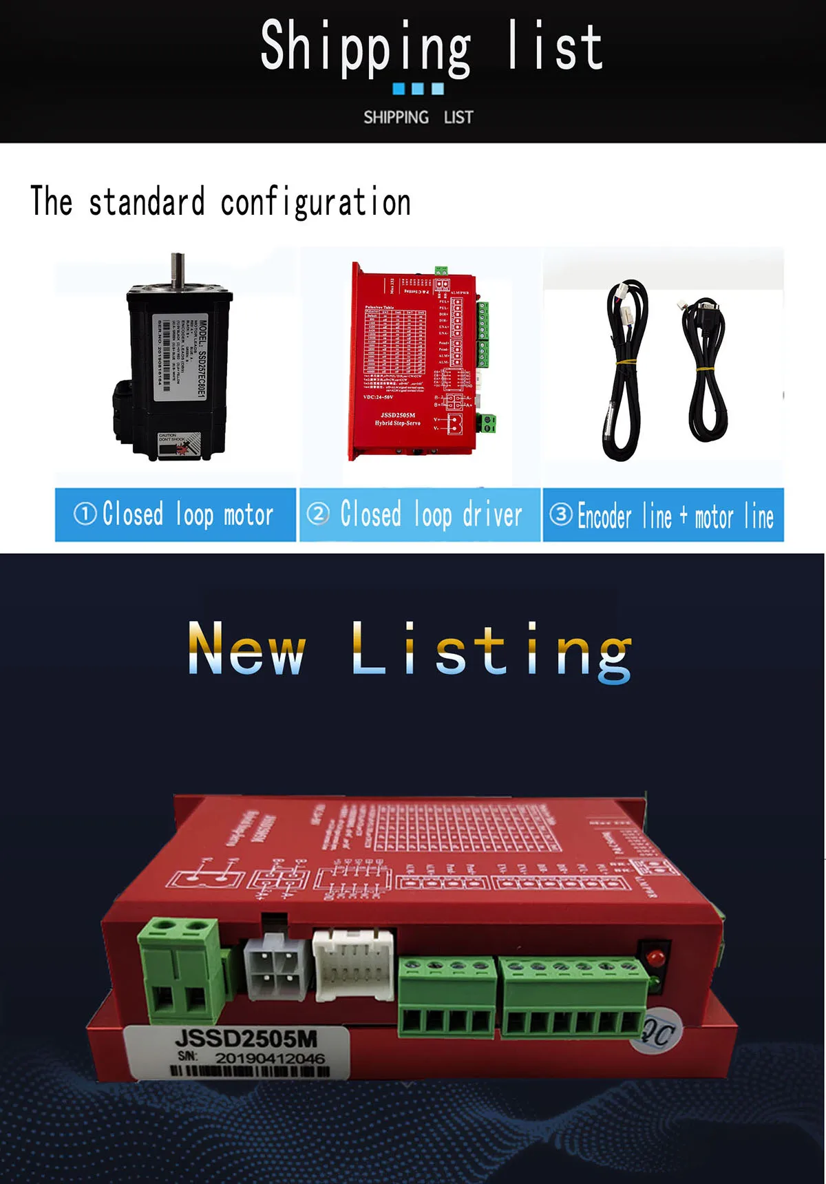
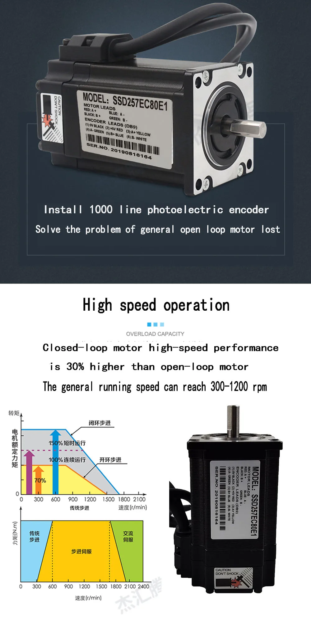
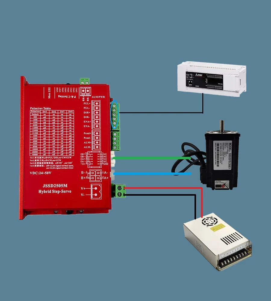
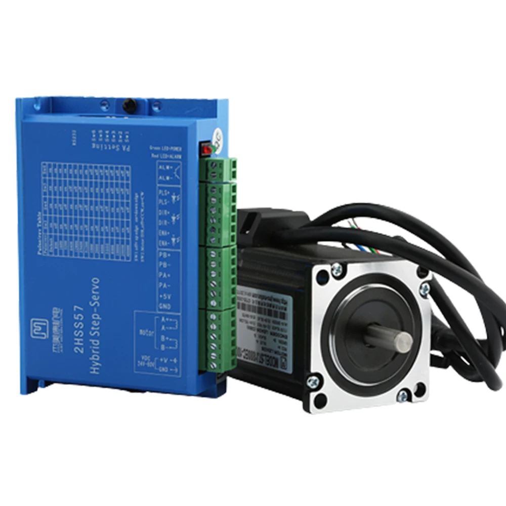
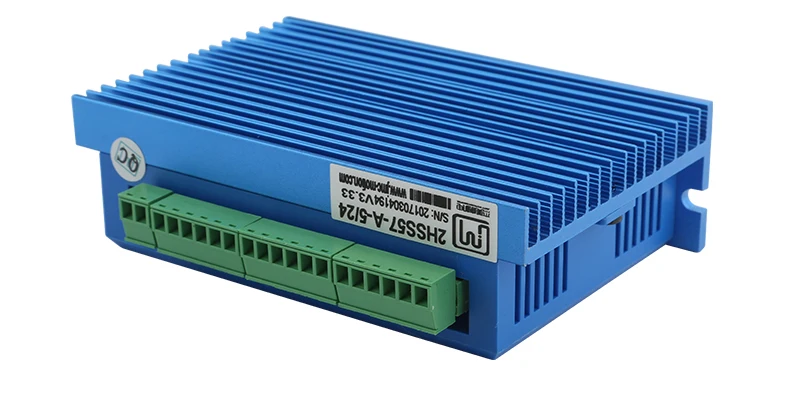
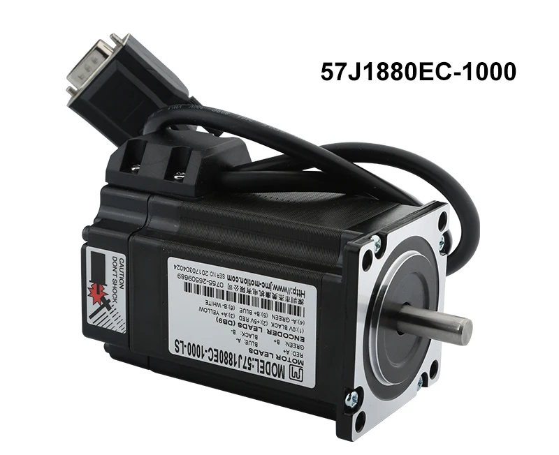
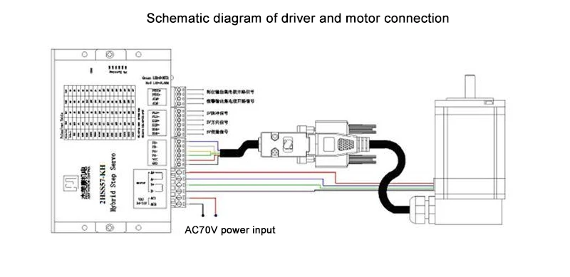
JSSD2505M hybrid step servo drive system is a perfect integration of servo control technology in digital stepping drive. The product adopts typical three-loop control method (position loop, speed loop and current loop), which is compatible with both stepping and servo. Drive a two-phase hybrid stepper motor. It is a very cost-effective motion control product.
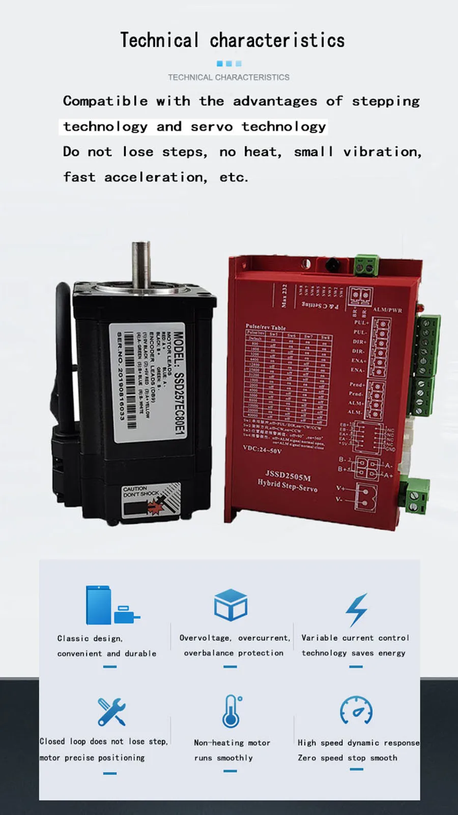
main feature:
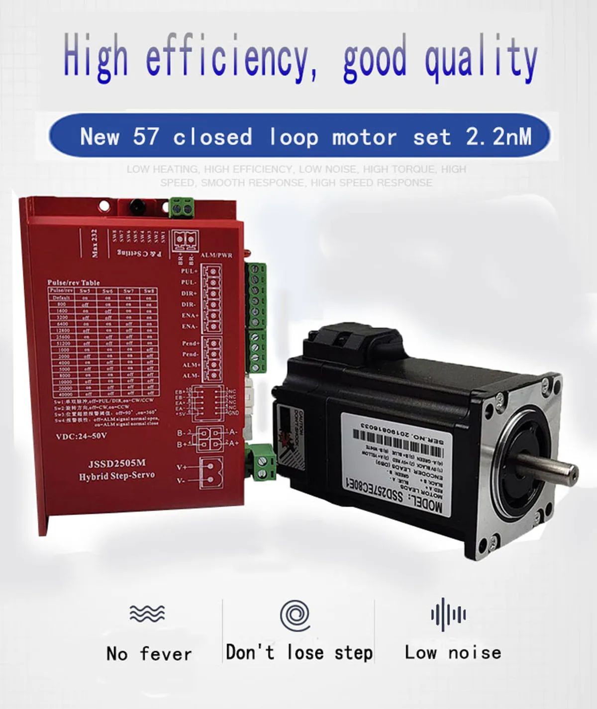
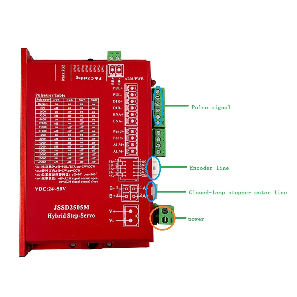
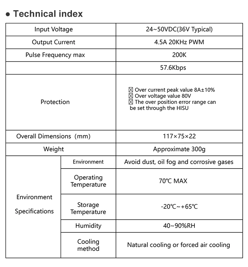
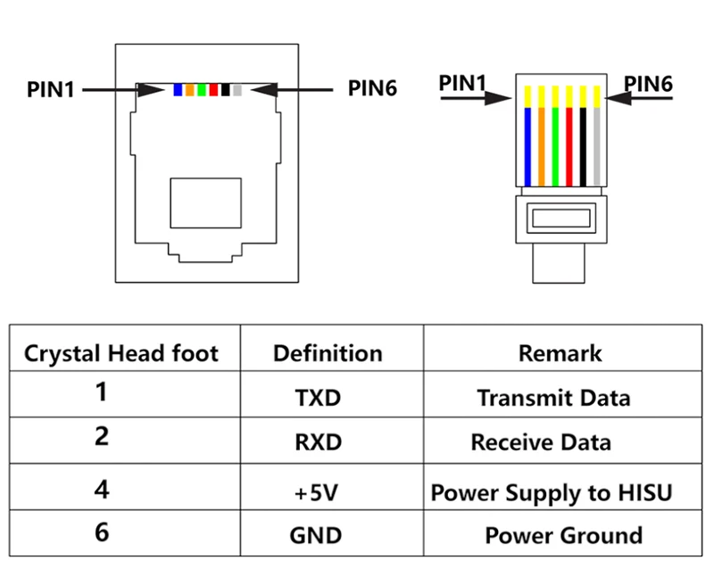
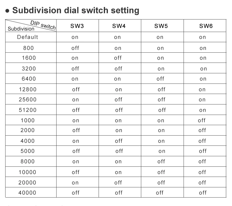
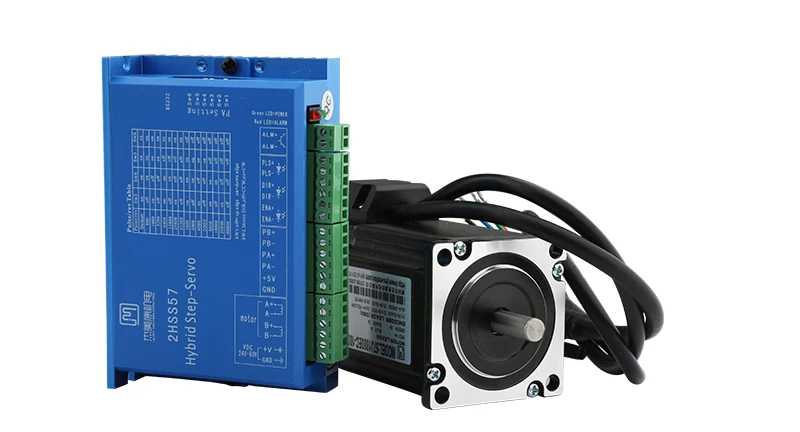
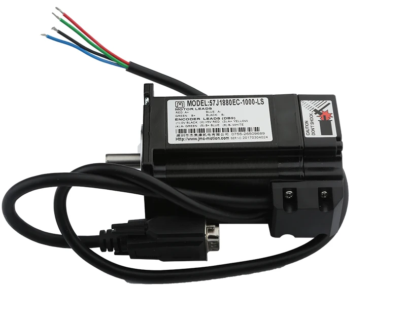
1): Full-closed control, the motor is equipped with 1000 line encoder, close to 100% torque output, subdivision setting range is 2-256, high speed response, high speed2): Optical isolation fault alarm output interface ALM, current loop bandwidth (-3dB) 2KHz (typical), speed loop broadband 500Hz (typical)3): Position loop broadband 200Hz (typical), can be downloaded or changed parameters with RS232 serial communication4): overcurrent, I2T, overvoltage, undervoltage, overheating, overspeed, out of tolerance protectionDetails of Motor:Motor model: SSD257EC80E1Motor current: 4AOutput torque: 2.2N.mBody length: about 99MMOutlet mode: single output shaftRated speed: 1000 rpm (no-load speed: 2000 rpm)Outlet mode: two-phase four-wire (must be wired according to motor label)Details of Stepper Drive:Drive Model: HBS57 (Nema 23, for 57 stepper motor)Pulse Signal: 3.3V/5V/24V compatible. No string resistor requiredVoltage Range: DC16-50VSubdivision Setting: 800-51200 subdivisionThe new 32-bit DSP digital 57 closed-loop stepper motor driver, engraving machine, CNC equipment available. PWM current control, low noise, high speed torque is 40% larger than ordinary drives.
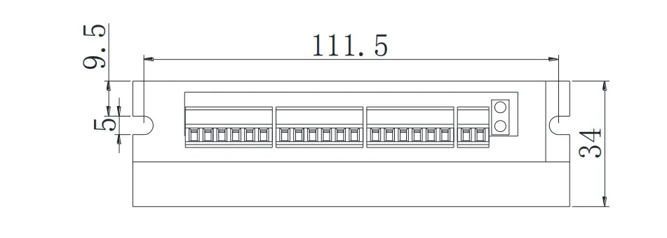
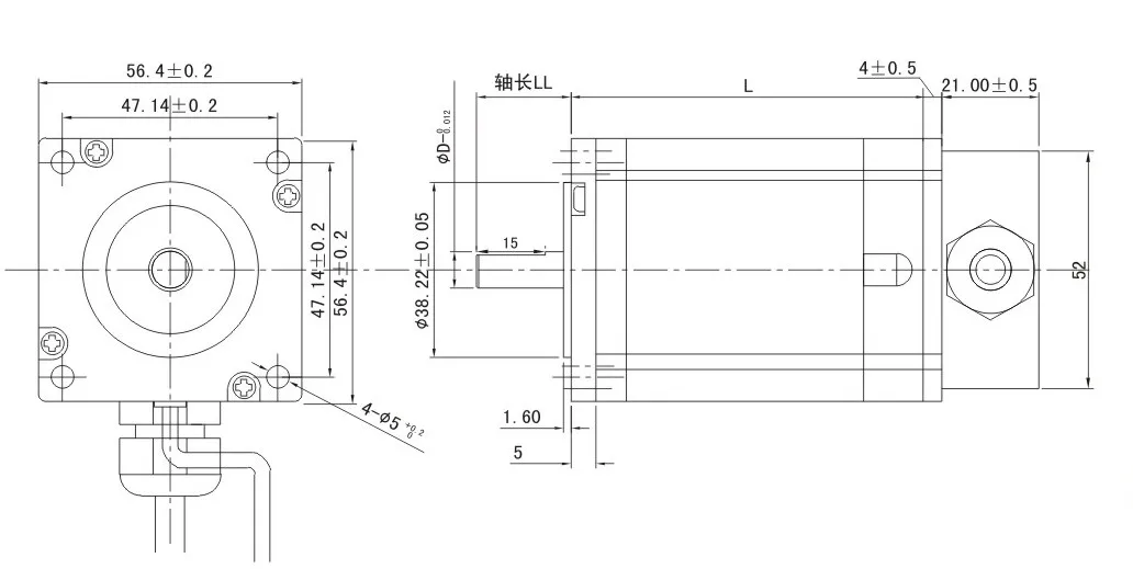
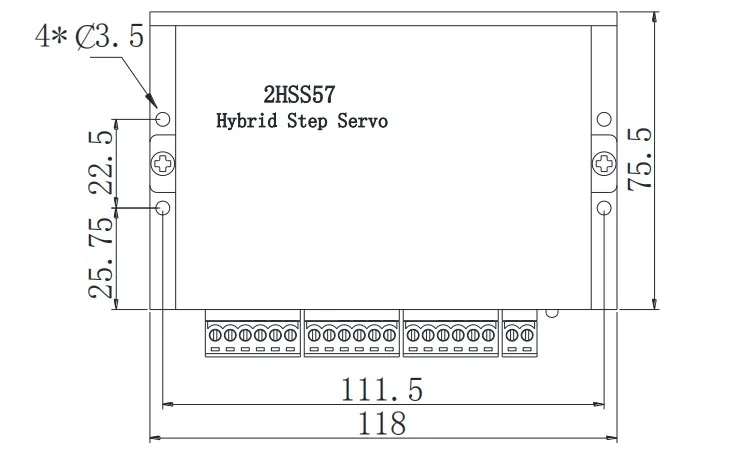
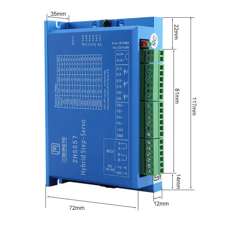
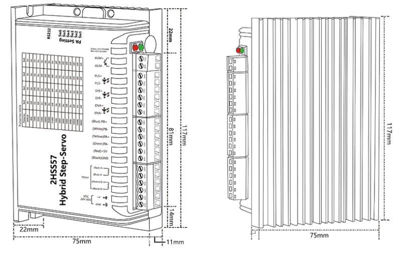
Size:
Nema23 2.0nm circuito fechado motor deslizante 57j1880ec-1000 1 driver de motor 2hss57 1 pces 3 metro codificador cabo
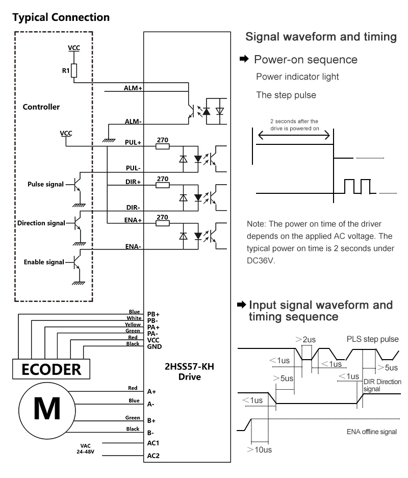
●performance introduction2HSS57 hybrid stepping servo drive system is a combination of servo control in digital stepping drive technology, the product uses a typical three-loop control method (position loop, speed loop and current loop) compatible with the dual advantages stepper and servo, suitable for driving two-phase hybrid stepper motors.
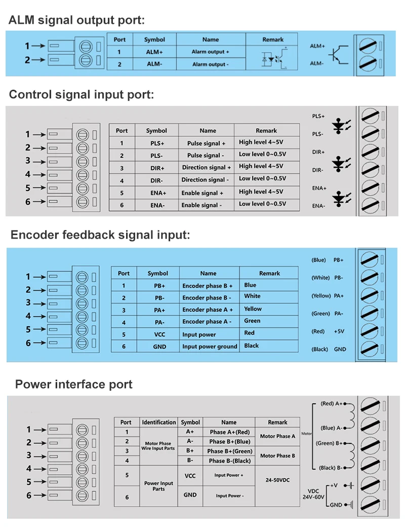
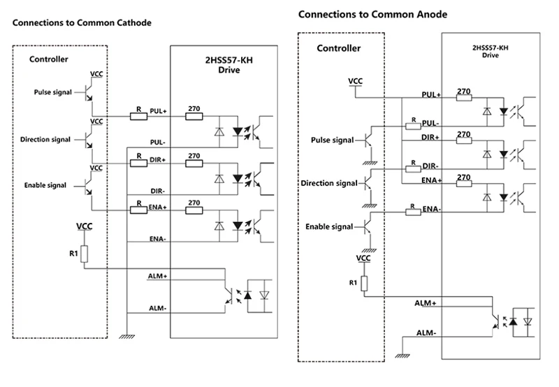
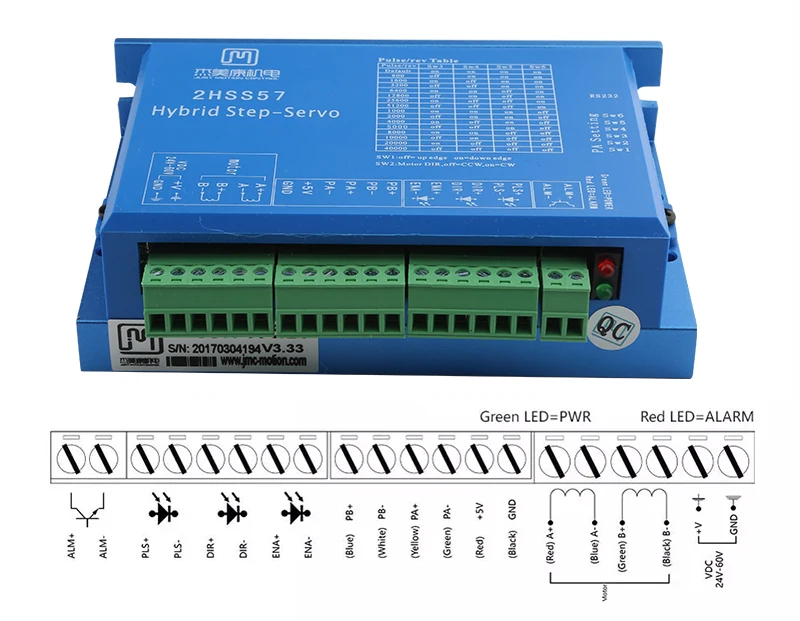
Note: if vcc = 5v, r = 0; if vcc = 12v, then r = 1k (power > 0.125w); if vcc = 24v then r = 2k (power > 0.125w); r1 (3-5k) must be connected to the control signal terminal.
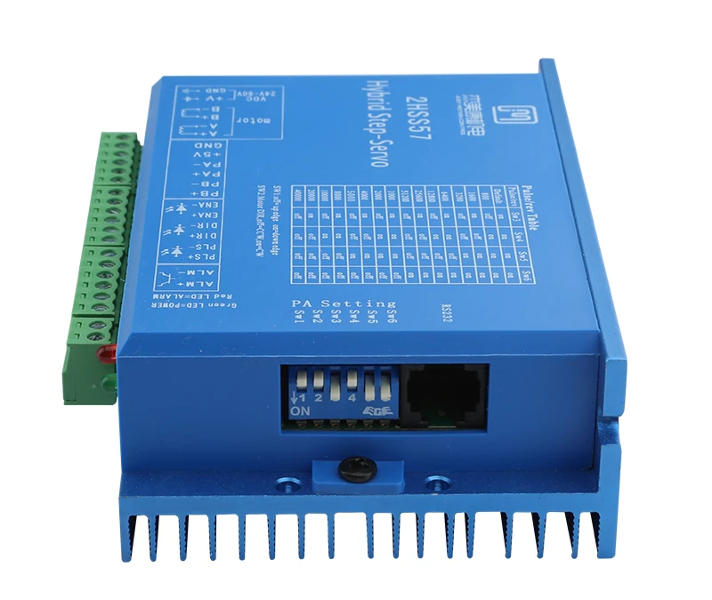
Input Margin Setting
Sw1 dip switch detects input edge setting, outside means rising edge is valid, in means falling edge is valid.
logic configuration directionWhen the sw2 dial switch is off or on, you can change the current motor movement direction, off=ccw,on=cw.
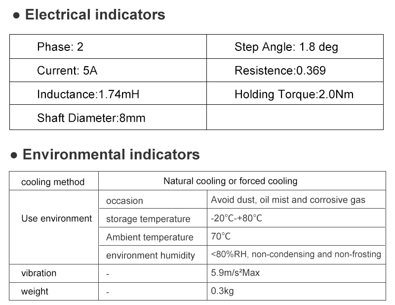
General Specifications:Stage 2 step angle: 1.8 degrees Current: 5th Resistance: 0.36inductance: 1.74mh Holding torque: 2.0nm Shaft diameter: 8mm
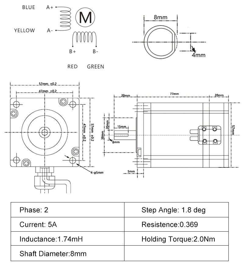
1. No losing step, high positioning accuracy 2. 100% rated output torque 3. 4. Small vibration, stable and reliable at low speed. Compatible with 1000 line encoder 5. Over current, over voltage, over position error protection
Main fields of applicationAdvertising, engraving, packaging, laser, electronics, medical, printing, carpentry, machinery, ceramics, stone, etc.Brief introductionThe two-phase hybrid stepping servo drive system integrates servo control technology into the digital stepping unit. It adopts typical three-loop control method, including current loop, speed loop and position loop. The product has the advantages of stepping and servo system, and it is an economical and efficient motion control product.Feature1. Totally closed loop control, motor encoder with 1000 lines, close to 100% of torque output 2. Section adjustment range is 2-256, with fast response speed and high speed, and optical interface beyond 3 of the insulation failure alarm output. Current loop bandwidth (-3 db) 2khz (typical value), Speed loop bandwidth 500Hz (typical value), Position loop bandwidth 200Hz (typical value) 4. rs232 series can be downloaded or parameters can be changed; overcurrent, overvoltage, undervoltage, overheat, overspeed, differential protection; clear entry alarm
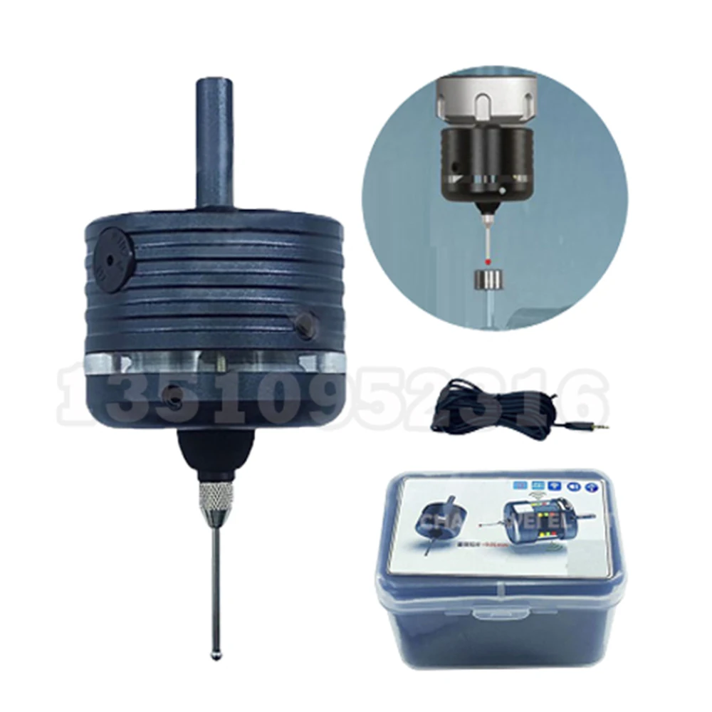
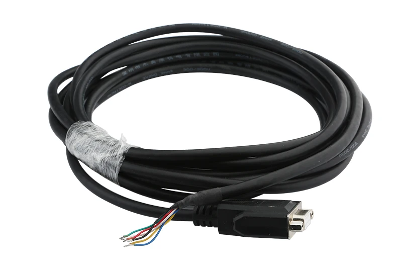
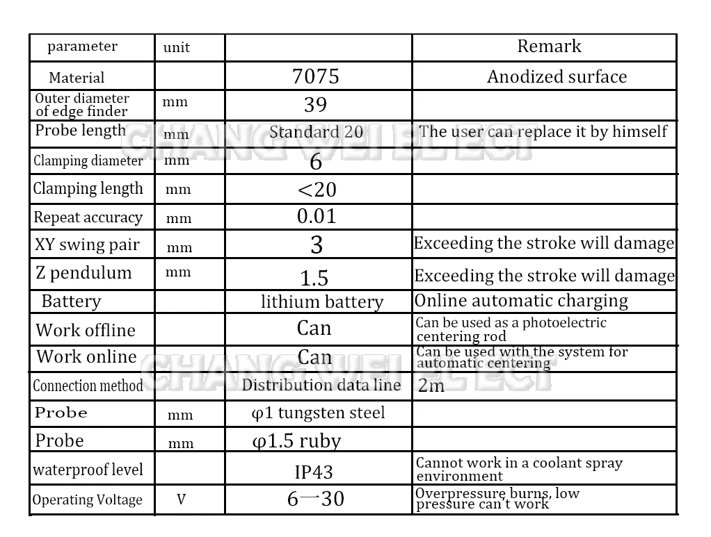
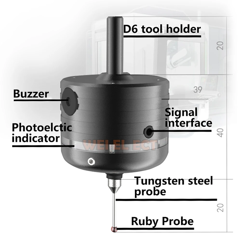
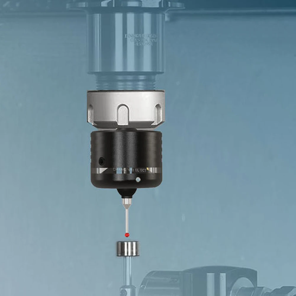
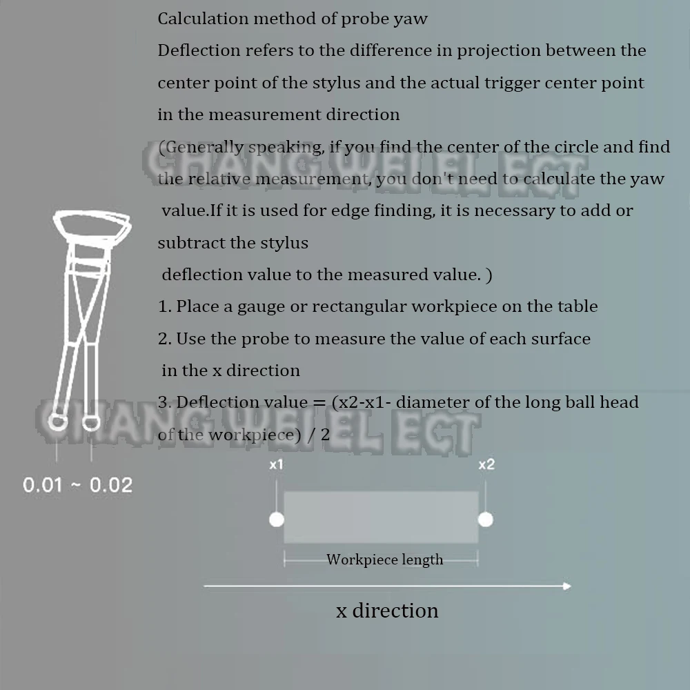
Three-dimensional edge finder 3d probe probe: The connection can realize online automatic measurement, and the offline can be used as a 5-direction acousto-optic splitter. One machine is multi-purpose, flexible and convenient, with high precision.1. The repeatability is 0.01.2. It can measure insulated workpieces.2. The probe signal NPN does not include the system wiring. You have to read the system manual for wiring. Generally support the tool setting instrument.Without wiring, it can be used as a photoelectric splitter.3. Send standard macro program.The difference between PCB plastic bracket version and all-metal reinforced version1. The appearance is basically the same. From the indicator window, the sandwich structure is the metal bracket version, and the pure white bracket is the pcb plastic bracket version. The difference in structure makes the repeat accuracy and stability of the two versions different.2. The pcb plastic bracket version has relatively low cost, and the structural stability is not as good as the all-metal bracket board.3. The all-metal bracket version, which fully refers to Renishaw's principle, has a relatively complex internal structure, high cost, repeatability and better structural stability.The difference between tungsten steel styli and ruby ??styliThe price of the two styli is the same, and the interface is M2.5. The roundness of tungsten steel is better than ruby. Durability is also better than tungsten steel.The working principle of the probeProbe triggerGnd and output signal line are connectedAfter the host computer obtains the signal, it realizes the functions of automatic centering and recording coordinates through the macro program.There are many types of systems on the market, and you have to complete the wiring macro program yourself.If you have the system supporting wiring and programming instructions, welcome to discuss wiring methods, system settings, and macro programming.After purchasing the probe, mach3 and grbl open source script programs can be provided.For CNC machine users, we can provide Renishaw standard macro programs.
Common problems and improvement methods1. Data line connection definitionThe red wire is 10 (signal), the white wire is GND, and the yellow wire is 0V (GND).2. Whether to turn on the spindle speed during detectionA. The edge finder is designed to withstand a maximum rotation of 600 rpm. High-speed rotation will damage the edge finder.B. When the data line is connected for automatic detection, the spindle cannot be opened, and the rotation will break the data line and damage the edge finder.C. When the data line is not connected, and it is simply used as an acousto-optic centering rod, it is also possible to turn on the main shaft to rotate at a speed of 600 rpm/min.Probing directly without opening the spindle.3. How to judge whether the home position of the edge finder is accurate after the trigger signal?After the edge finder is installed on the chuck, the table is rotated and adjusted to 0, and the probe is pushed by hand. After the probe is automatically returned to its position, rotate the edge finder to seeWhether the table value is a constant value.4. Why is the concentricity different after the precise edge finder is reinstalled on the main shaft and the central head?Every time the edge finder is reinstalled, the concentricity of the spindle and the chuck will be affected by the concentricity of the spindle and the chuck.Concentricity deviation of the probe into the edge finder.5. How to improve the detection accuracy when the CNC system of machine tool mechanical structure accuracy cannot be further improved.A. Rotate the center through the spindle at a speed of 600 rpm (this method can only be used for offline and non-connected work, if you need to rotate the edge finderAutomatic center detection, you can purchase a wireless edge finder to achieve)B. The deviation of the spindle and the chuck can be adjusted to the 0 position mark by making an edge finder on the spindle and the chuck.The fixed position and direction of the edge instrument relative to the central head and the main shaft is improved. (The most fundamental solution is to improve(Spindle and chuck accuracy)C. The signal processing response time of the edge finder is fixed at about 0.0005 +0.0001s, but various grades of numerical control systems and configurationFor sets of circuits, the delay consistency is quite different. When the probe is approaching the measured surface, try to reduce the axis movement speed, which can beIn order to reduce the error caused by the delay consistency problem.

Origin : Mainland China
Model Number : DDCSV4.1 NEMA23 kit